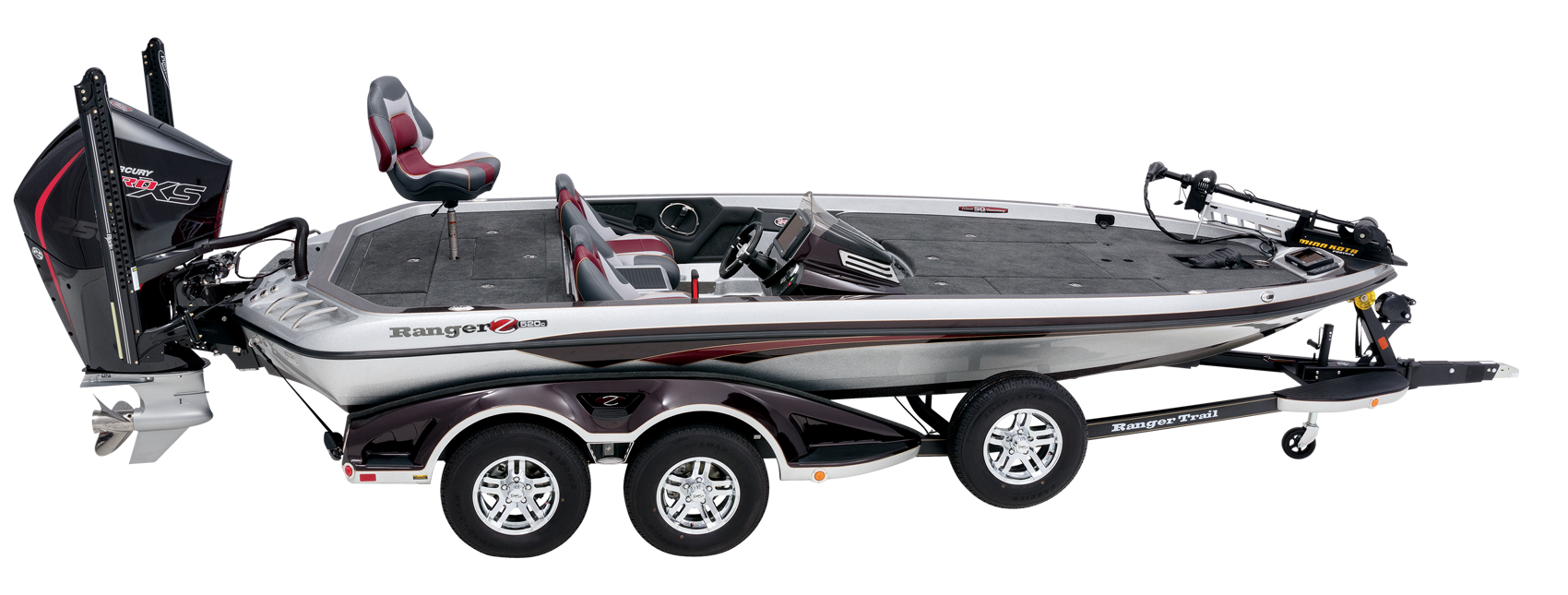
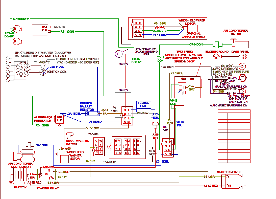
I really enjoy my boat, but such was not always the case. When I first got the boat the keys had been lost, so I did extensive research to find what my optio. Wiring Diagram 1992 Ranger Boat.pdf owner's manuals - ranger boats ranger boats owner's manuals. Click your boat segment below to access a current downloadable owner's manual 1992 ford ranger wiring diagram - wiring forums 1992 ford ranger wiring diagram to 2011 45 92 econoline, size: 800 x 600 px, source: carlplant below are some of the top illustrations we get.
Assortment of polaris ranger ignition wiring diagram. A wiring diagram is a streamlined conventional pictorial representation of an electric circuit. It shows the elements of the circuit as streamlined forms, and the power and also signal links in between the devices.
A wiring diagram normally offers information concerning the family member placement and setup of gadgets and terminals on the tools, in order to help in structure or servicing the gadget. This is unlike a schematic diagram, where the plan of the elements’ interconnections on the diagram normally does not correspond to the parts’ physical places in the completed device. A photographic layout would reveal a lot more detail of the physical appearance, whereas a wiring diagram utilizes a more symbolic symbols to emphasize affiliations over physical appearance.
A wiring diagram is typically utilized to troubleshoot troubles as well as making sure that all the connections have actually been made which every little thing is present.

polaris ranger ignition wiring diagram
Wiring Diagram Pictures Detail:

- Name: polaris ranger ignition wiring diagram – i do have a 1996 polaris sl700 i need information regarding the rh justanswer GM Ignition Switch Wiring Diagram GM Ignition Switch Wiring Diagram
- File Type: JPG
- Source: 107.191.48.154
- Size: 571.73 KB
- Dimension: 1411 x 1584
Wiring Diagram Sheets Detail:
- Name: polaris ranger ignition wiring diagram – Polaris Ranger Ignition Wiring Diagram Awesome 2010 Polaris Ranger 800 Xp Wiring Diagram 2001 Ignition
- File Type: JPG
- Source: magnusrosen.net
- Size: 455.26 KB
- Dimension: 1475 x 970
Collection of polaris ranger ignition wiring diagram. Click on the image to enlarge, and then save it to your computer by right clicking on the image.
Exactly What’s Wiring Diagram?
A wiring diagram is a sort of schematic which makes use of abstract photographic symbols to reveal all the affiliations of components in a system. Wiring representations are made up of two points: icons that represent the parts in the circuit, as well as lines that stand for the connections in between them. Therefore, from wiring diagrams, you understand the family member place of the parts as well as how they are connected. It’s a language engineers should learn when they work on electronics tasks.
Wiring Diagram VS. Schematics
It’s very easy to get confused concerning circuitry diagrams as well as schematics. Wiring diagrams mainly reveals the physical setting of components and also connections in the built circuit, yet not necessarily in reasoning order. It decreases integrated circuits right into sub-components to make the system’s practical reasonings much easier to recognize.
[Exactly How to|Ways To|The Best Ways To|How You Can]@ Check Out Wiring Diagram
Recognize Wiring Diagram Symbols
To review a wiring diagram, initially you need to recognize just what basic elements are included in a wiring diagram, and also which pictorial icons are made use of to represent them. The usual aspects in a wiring diagram are ground, power supply, cable as well as connection, outcome tools, buttons, resistors, reasoning entrance, lights, and so on. A list of electrical symbols and also summaries can be found on the “electric symbol” page.
Line Joint
A line stands for a cord. Cables are utilized to link the components with each other. There should be a legend on the wiring diagram to tell you exactly what each color implies.
Types of Link
A collection circuit is a circuit in which elements are connected along a solitary path, so the existing flows through one element to obtain to the next one. In a collection circuit, voltages add up for all components attached in the circuit, and also currents are the very same with all parts.
Tips to Attract Good-looking Wiring Diagrams
A great wiring diagram has to be practically proper and also clear to check out. Look after every information. The representation ought to reveal the proper direction of the favorable and also negative terminals of each element.

Utilize the best signs. Discover the definitions of the fundamental circuit icons as well as pick the correct ones to utilize. Some of the symbols have actually close look. You have to be able to tell the differences before using them.
Attract linking wires as straight lines. Make use of a dot to indicate line junction, or usage line leaps to suggest cross lines that are not connected.
Label elements such as resistors and also capacitors with their worths. See to it the message positioning looks tidy.
In general it is great to place the favorable (+) supply at the top, and also the negative (-) supply at the base, as well as the sensible circulation from left to.
Aim to organize the placement decreasing cord crossings.
Variety of polaris ranger ignition wiring diagram you’ll be able to download free of charge. Please download these polaris ranger ignition wiring diagram by using the download button, or right visit selected image, then use Save Image menu.
What is a Wiring Diagram?
A wiring diagram is a simple visual representation of the physical connections and physical layout of an electrical system or circuit. It shows the way the electrical wires are interconnected and will also show where fixtures and components could be connected to the system.
Wiring diagrams help technicians to see how the controls are wired to the system. Many people can read and understand schematics known as label or line diagrams. This type of diagram is much like going for a photograph in the parts and wires all connected up.
polaris ranger ignition wiring diagram
Wiring Diagram Pics Detail:
- Name: polaris ranger ignition wiring diagram – Trend 2010 Polaris Ranger 800 Xp Wiring Diagram Blonton Simple Schematic Dolgular
- File Type: JPG
- Source: sidonline.info
- Size: 125.39 KB
- Dimension: 563 x 970
Wiring Diagram Images Detail:
- Name: polaris ranger ignition wiring diagram – Polaris Ranger Ignition Switch Wiring Diagram – anonymerfo
- File Type: JPG
- Source: biztoolspodcast.com
- Size: 48.92 KB
- Dimension: 600 x 413
Wiring Diagram Pictures Detail:
- Name: polaris ranger ignition wiring diagram – Wiring Diagram For Polaris Razr 800 – yhgfdmuor · Polaris Ranger Ignition
- File Type: JPG
- Source: altaoakridge.com
- Size: 64.03 KB
- Dimension: 542 x 340
Wiring Diagram Pictures Detail:
- Name: polaris ranger ignition wiring diagram – polaris atv wiring wire center u2022 rh moffmall co 2001 Polaris Sportsman 90 Wiring Diagram Polaris Sportsman 500 Wiring Diagram
- File Type: JPG
- Source: g-news.co
- Size: 1.53 MB
- Dimension: 1372 x 2107
Wiring Diagram Images Detail:
- Name: polaris ranger ignition wiring diagram – 2015 Polaris Ranger Xp 900 Wiring Diagram Somurich
- File Type: JPG
- Source: szliachta.org
- Size: 265.13 KB
- Dimension: 1024 x 673
Wiring Diagram Pictures Detail:
- Name: polaris ranger ignition wiring diagram – Polaris Ranger Ignition Switch Wiring Diagram – davidbolton
- File Type: JPG
- Source: altaoakridge.com
- Size: 85.40 KB
- Dimension: 399 x 453
What can be a Wiring Diagram?
A wiring diagram is a simple visual representation from the physical connections and physical layout of your electrical system or circuit. It shows what sort of electrical wires are interconnected and can also show where fixtures and components could possibly be connected to the system.
When and How to Use a Wiring Diagram
Use wiring diagrams to assistance with building or manufacturing the circuit or digital camera. They are also helpful for making repairs.
DIY enthusiasts use wiring diagrams but they’re also common in home building and auto repair.
For example, a home builder should what is geographic location of electrical outlets and light fixtures utilizing a wiring diagram to prevent costly mistakes and building code violations.
How is a Wiring Diagram Different from a Schematic?
Ranger Boat Ignition Switch Manuals
A schematic shows the master plan and function on an electrical circuit, but is not interested in the physical layout of the wires. Wiring diagrams show what sort of wires are connected and where they need to based in the actual device, along with the physical connections between every one of the components.
How is really a Wiring Diagram Different from the Pictorial Diagram?
Unlike a pictorial diagram, a wiring diagram uses abstract or simplified shapes and lines to demonstrate components. Pictorial diagrams are often photos with labels or highly-detailed drawings from the physical components.
Standard Wiring Diagram Symbols
If a line touching another line features a black dot, it indicates the lines are connected. When unconnected lines are shown crossing, you’ll see a line hop.
Most symbols utilized on a wiring diagram resemble abstract versions with the real objects they represent. For example, a switch might be a enter the line which has a line at an angle to the wire, just like an easy switch it is possible to flip don and doff. A resistor will probably be represented which has a compilation of squiggles symbolizing the restriction of current flow. An antenna is a straight line with three small lines branching off at its end, just like an actual antenna.
Ranger Boat Ignition Switch
Wiring diagram symbols
Boat Ignition Switch Troubleshooting
- Wire, conducts current
- Fuse, disconnect when current exceeds a particular amount
- Capacitor, accustomed to store electric charge
- Toggle Switch, stops the flow of current when open
- Push Button Switch, momentarily allows current flow when button is pushed in, breaks current when released
- Battery, stores electric charge and generates a continuing voltage
- Resistor, restricts current flow
- Ground wire, employed for protection
- Circuit breaker, utilized to protect a circuit from an overload of current
- Inductor, a coil that generates a magnetic field
- Antenna, transmits and receives radio waves
- Surge protector, accustomed to protect a circuit from the spike in voltage
- Lamp, generates light when current flows through
- Diode, allows current to flow in one direction indicated by an arrowhead or triangle on the wire
- Microphone, converts sound into electrical signal
- Electrical motor
- Transformer, changes AC voltage from high to low or vice versa
- Headphone
- Thermostat
- Electrical outlet
- Junction box
Related Articles: